Why is it so hard to mimic depth blur in Fusion(and how to make it work) ?
I was once asked by a friend of mine how to use the Z-channel from a 3D render to recreate a DoF blur on a CG render. That was where I realized that doing something thought to be straightforward was quite complex for beginners in Fusion, especially if you come from software that takes you by the hand.
The theory(skip to “How to do it” if you’re not interested):
I’ve been obsessed with convolution for some time. When watching videos on the topic, I realized how dependent the world we live in is on this wonderful tool.
Convolution has applications that include probability, statistics, acoustics, spectroscopy, signal processing and image processing, geophysics, engineering, physics, computer vision and differential equations.
Being a hobbyist photographer, the application that fascinates me the most is how we can use this mathematical tool to blur images. I recommend this wonderful video by 3Blue1Brown to discover the basics of convolution: https://youtu.be/KuXjwB4LzSA?si=a29ydkmt7cTuTrri&t=512
But what is it anyway ?
Imagine a checkerboard representing our image, with each square being a pixel. The main idea of convolution in image processing will be to sample each pixel and run it through a device that will produce a new value for each of these pixels. This device is actually a matrix, which in its most basic form looks like this:
A 3×3 matrix.
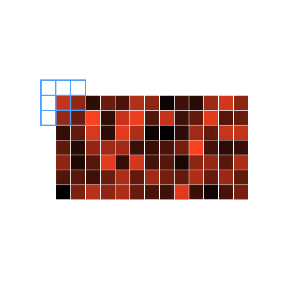
The kernel running through all the pixels of an image.
In image processing terms, this matrix is called a kernel. We slide this kernel over each pixel of our image to perform calculations. But what mathematical operations does convolution apply to the pixel values, and how are the kernel's coefficients determined?
The coefficients used in this kernel will depend on the use case; we’ll get back to that later. For example, in the case of a classic box blurring filter, the coefficients are set to:
A basic box blur filter kernel
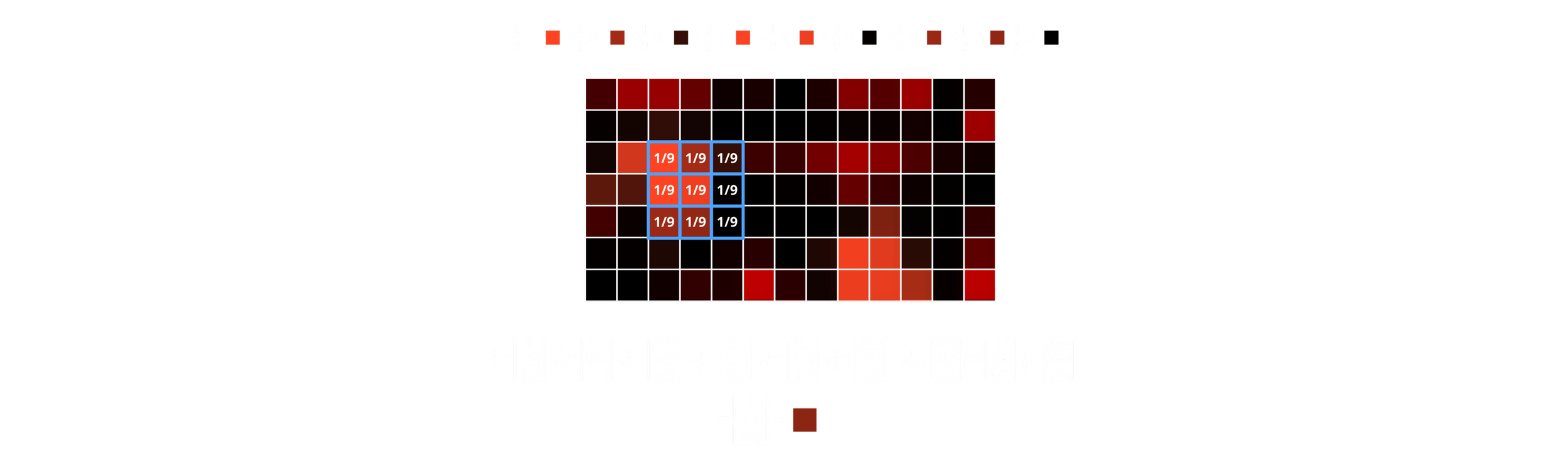
When traversing each pixel of the image, the following operations occur:
For each overlapping element between the kernel and the image, multiply the pixel's value by the corresponding kernel coefficient. Repeat this for every pixel under its corresponding value in the kernel, and then sum the stored values. In other words: the resulting value of a given pixel is the sum of every product between the kernel coefficient and its corresponding pixel. For coordinate in the convolution result of a 3x3 image, the value would be:


Here’s a visual representation of how a box blur filter works (I’m getting tired of matrixes):
Source: https://www.algorithm-archive.org/contents/convolutions/2d/2d.html
As you can see, each pixel's color bleeds onto its neighbors, as we are averaging the pixel values. This creates the illusion of blurring the image. (Note that since the area outside the image is not defined, when the kernel is placed on a border row or column, it will not know what value to use for the calculation. Multiple options are possible for handling this: https://en.wikipedia.org/wiki/Kernel_(image_processing)#Edge_handling)
Note that, since we are working with colors (in an RGB system), the pixel value is actually three-dimensional [r, g, b]:
Yes, I picked every color by hand to get the r,g,b values.
Each coefficient of the kernel multiplies the 3x1 matrix representing the pixel's color coefficients.
And there you have it, the new color of the pixel! Repeat this process for every pixel in the image, and you’ll have successfully applied a box blur filter.
But, do we really need this much theory ?
You thought we were going to talk about Fusion, and we’re just “having fun” with matrices, so what gives? We’re getting there; there’s just a little more we need to know before firing up Fusion.
My kernel is bigger than yours !
We haven’t talked yet about how to vary the intensity of the blur. My first instinct was that we could achieve this by modifying the kernel values, but I was wrong.

The influence of aperture on the blurriness of an image.
The amount of blurriness (as well as the depth of field) of a photo coming out of a camera varies according to the diameter of the aperture in the lens. A larger aperture will result in a blurrier image, whereas a smaller one will do the opposite.
If you look at the following illustration, you’ll see that in the first case, the rays coming from out-of-focus objects 1 and 3 are more spread out on the focal plane due to the angle at which they enter the lens.
Conversely, when you shut down the aperture, the rays coming from the most extreme positions of the lens are blocked out, resulting in less spreading and thus a sharper image.
Now, if we go back to the digital realm, we could translate this concept of a larger aperture to having a more pronounced bleeding of colours between pixels, thus, a larger kernel. So in order to vary the intensity of the blur, we’ll vary the size of the kernel, as demonstrated in this image:
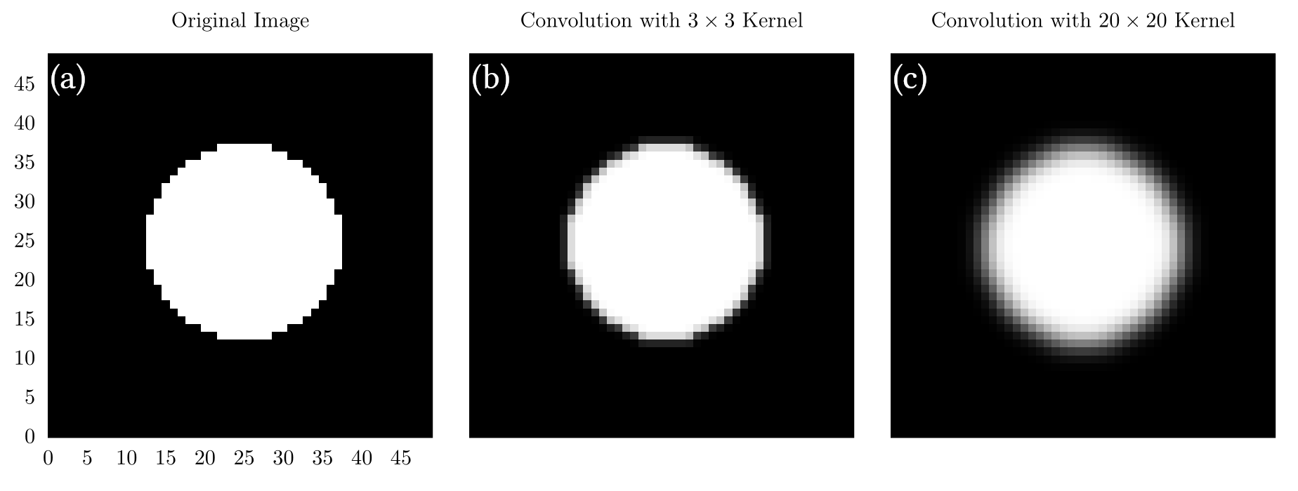
As you can see, in the image with a 3x3 kernel, the edges are much less blurred than with the 20x20 kernel. This is logical, as a larger kernel averages values over a greater area, allowing for a wider spread of pixel values.
Maybe, but mine is way softer !
“OK, we’ve changed the size of the kernel, but what about it's coefficient ?”
You might have already come across different types of blur in various software: Box, Gaussian, Bartlett… For example, when you use a box filter on an image, the result you’ll get might seem of lesser quality than a Gaussian blur. The reason for this is that their kernels use different coefficients.
As we’ve seen previously, a box blur uses the following kernel:
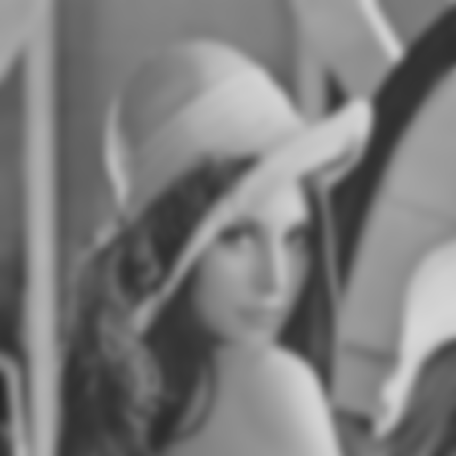
With all coefficients are equal, the matrix is uniform. For now, we’ve only seen very low-resolution images, but with higher resolutions, we might run into a problem. Since the kernel is uniform, the resulting image will suffer from a rough averaging of the neighboring pixel values, and in some cases, patterns might appear in the blur, which can be problematic.

Do you see the blocky pattern in the hair ?
To address this problem, we’ll have to change the distribution of the coefficients of the kernel. In order to get a smoother averaging of pixel values, we can use a Gaussian distribution:

The value of the coefficients have been sampled from a 3D gaussian distribution
Gaussian Blur: note that now, the blurring is much softer, particularly in the hair.

Box Blur
What’s interesting here is that we can truly customize the appearance of our blur, depending on the distribution of the kernel values. This opens doors to many new possibilities. We can visualize the difference between each kernel using their respective 3D representations:
A 3D gaussian distribution
A 3D Box Filter distribution
Let’s get 3d-ed
“OK, we can change the type of blur and its intensity, but it always applies uniformly to the image !”
We actually have all the ingredients required to mimic a depth-of-field effect. We only need one more thing: depth.
Everything we’ve done so far has been in the 2D realm. We have applied different types of blur at different intensities, but always uniformly across our image. What we need to mimic the DoF of a lens is to know at what distance from the optical center of the lens any given point of the image was located.
When we focus a lens while shooting with a camera, we are choosing the range of distances within which the image will be sharp, and where it will be blurry. We can define 'sharp' as when a single point, passing through a lens, does not cover more than a single pixel in the resulting image. The farther we move from the zone of sharpness, the blurrier the image gets. In other words, depending on where the object is located on the optical axis, or at what depth, the resulting resolution of the object will vary.
Remember that to vary the intensity of a blur filter, we change the size of the kernel. So, in theory, if we have access to the depth information of the image at a pixel level, we’ll be able to vary the size of the kernel accordingly, and thus the blur.
That’s the whole challenge.
How to do it ?
Everything we discuss here can be applied to real photography and video. Since AI models are getting better, it’s getting easier to obtain high-quality depth maps from live-action footage. As I’m more inclined to CGI, I’ll be using such material to demonstrate the purpose of this article. But what we do here with CG can also be done with live-action footage, since the concepts are the same.
I’ve always liked to be able to change things after the fact, and that applies to DoF in 3D rendering. I always render without applying DoF, as I believe it is better to do it in compositing, since it cannot be undone once it’s baked in. We don’t want to re-render because we later think that the DoF is too shallow or too wide. And if, like me, you happen to work at unrealistic scales in your 3D scenes because you’re distracted, dialing this focus distance slider can sometimes be very tricky.
The problem with Fusion
Even if I’m a fanatic of Fusion, I have to admit that Nuke has a better way of doing a Depth Blur. Everything has been designed for efficiency, and there’s no guesswork involved in how to do it (probably because of the abundance of online training resources). But with Fusion, it’s different; you have to get your hands a little dirtier to get to where you want to go. Yet, even there, some elements (which I deem very important) are missing; we’ll get back to that in the conclusion.
“I can just take a blur node and use the effect mask input to vary the intensity my Depth Map !”
Well, no. What happens when you do that is the blur is uniformly applied to the entire image, as seen above, then the Z map will just change the opacity of the affected image, gradually mixing the original image with the blurred image. The result? I don’t even want to show it here. Trust me, it’s horrible.
In Fusion, the “official way” to achieve a Depth Blur effect is to use the Depth Blur node. What this node does is to use the Z information of each pixel to run a convolution, with a kernel size depending on that depth information, resulting in a blurrier image where the input value is higher. Brighter = larger kernel = blurrier.
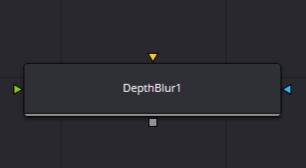
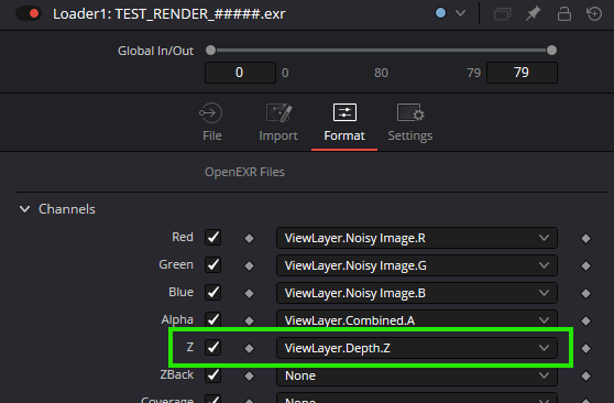
The orange input is your image, and the green input is your depth information. Note that you don’t need to have a Z channel in your image channels, but it’s better, since the channel used will be set to Z by default. To do that, go to your loader node and choose Format. In the Z field, choose the corresponding layer from your multilayer file. Now, when you press Z in the viewport, you’ll see the Z channel of your flow. Note that you’ll potentially have a full black or full white image, and this is the cause of our problem.
It’s very important to make sure your image is scene-referred as opposed to display-referred*. To put it simply, if you’re not familiar with this concept, scene-referred imagery refers to a state in which your image stores data proportionally to the physical intensity of a property. No post-processing has yet been applied to it. This image cannot be displayed on a regular screen because its maximum brightness will potentially be much higher than what your monitor can achieve. That also doesn’t account for the absence of a gamma curve, but that’s another subject.
For our Z map, we need to have scene-referred, linearly-encoded values, as they will directly drive the intensity of the blur: going twice as far in the scene must result in double the Z data value. We’ve been used to considering that the data passes we use in compositing are colors. But they’re not; they’re just data that are stored in an image-like array, which are displayed without interpretation on a monitor that is very specific about what intensity it can handle. So, when a pixel is at 15m for the camera, the value could potentially be 15 in R, G, B! Since the maximum luminance is usually associated with the value 1, a value of 15 will be completely out of reach for any display. That is why, most of the time, you will have white Z passes; it’s not clipped, it’s just that your display can’t handle it.
Note that some renderers allow you to directly remap the values from the min/max values between 0 and 1, like Redshift for example, where you can normalize the Z in the AOV manager. In the Blender compositor, you can use the normalize node to map the min and max distance values between 0 and 1.
*I believe that even if you render display-referred images, the Z-Depth won’t be affected by tone mapping or gamma adjustment. At least, I don’t know any renderer that does this to the depth pass, but who knows…
What now ?
We have exactly what we need, right ?
In the concept, yes. In application, no. Why ?
Because the controls of this node are crap ! Let’s look at how does it work:
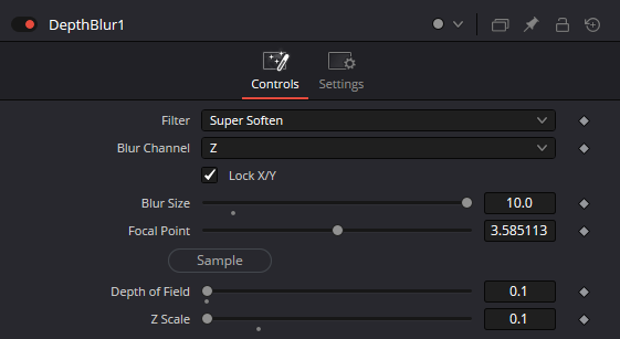
Filter type: You can choose the type of kernel you want. But you can only choose between Box (yes, Box), Soften, and Super Soften.
Blur Channel: Whether you want to use the R, G, or B channel to drive the effect, in case you haven't set your Z properly.
Blur Size: This value uniformly scales up or down the kernel size, resulting in a globally blurrier image.
Focal Point: Pick on the viewer where you want your image to be sharp, where to set the kernel size to 0.
Depth of field: How far from the sharp zone the kernel size starts to rise. How deep the zone of sharpness extends in the image.
Z Scale: Defines the range of values from the depth map that will be used to drive the effect.
Now, why this is problematic:
These types of kernels are really not suitable for mimicking the DoF of a lens. There are much cleaner kernels that can be used for that.
If you have a depth map that isn't normalized by default, you’ll have to deal with extremely small values in the DoF and Z Scale sliders. This is a real pain; these sliders aren't made to work at such small scales. You move your mouse a pixel to the right, and the effect will either vanish or completely explode, making this tool just unusable.
One good point, though, is that you can pick the Z value directly from your image, which means less guesswork. Apart from that, anyone who has already tried to use this depth blur will attest it’s shit.
So, we’re fucked ?
Of course not! I've got a solution for you.
Of course, it won't be as good as a perfectly working node, but you will definitely get better results.
There's another node in Fusion that can be used to convolve an image with a kernel whose size depends on another parameter. Ladies and gentlemen, please meet the VariBlur:
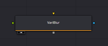
It's actually very similar to the DepthBlur node. It uses the same inputs: the image to blur and a depth map (connected to the 'Blur Image' input). Note that this node is quite resource-hungry, so don't expect exceptionally fast performance when using it.
Even at first glance it looks better.
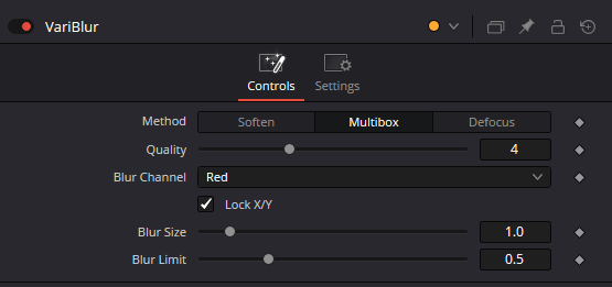
I like the smell of VariBlur in the moring…
You see that we can use a new method called Defocus. I don’t really know how it works, but I’m pretty sure it uses convolution like the other modes with a somewhat different kernel. In my opinion, this mode gives the best results of all.
If you try to use the VariBlur node like this, there's still a good chance it won't work. Again, this is because your Z map might not be normalized. Also, don't forget that your Depth map is similar to a black and white gradient, and the most blurred pixels will be where the Depth map has the highest values. Therefore, the effect won't be exactly what we want because it lacks proper depth of field control. We’ll fix that later; for now, let’s normalize this depth map to a range of 0 to 1.
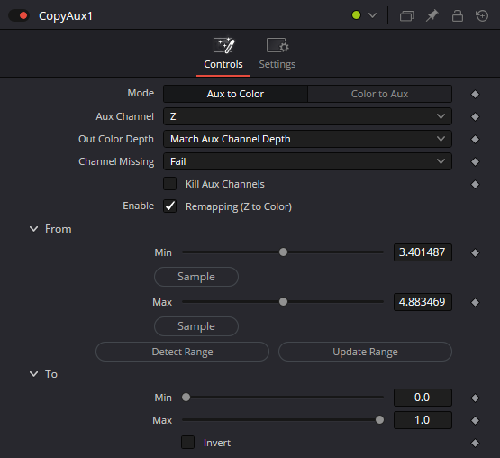
I didn’t find any other way to do it than by using a node called Copy Aux. I guess we could do it with a color curve, but since depth values can be pretty extreme, it would be quite tricky.
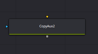
You can think of the Copy Aux node as a way to extract or inject data from and into channels beyond R, G, B, such as Z, N, UV, etc. It’s similar to Nuke’s "Shuffle" node. We’re using it here for its remap function, as well as the fact that the defocus node doesn't support the Z channel as an input.(Arrrgghhh…)
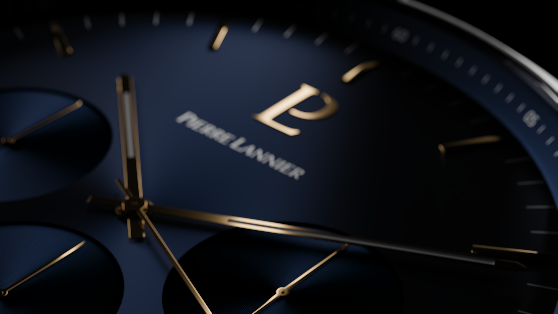
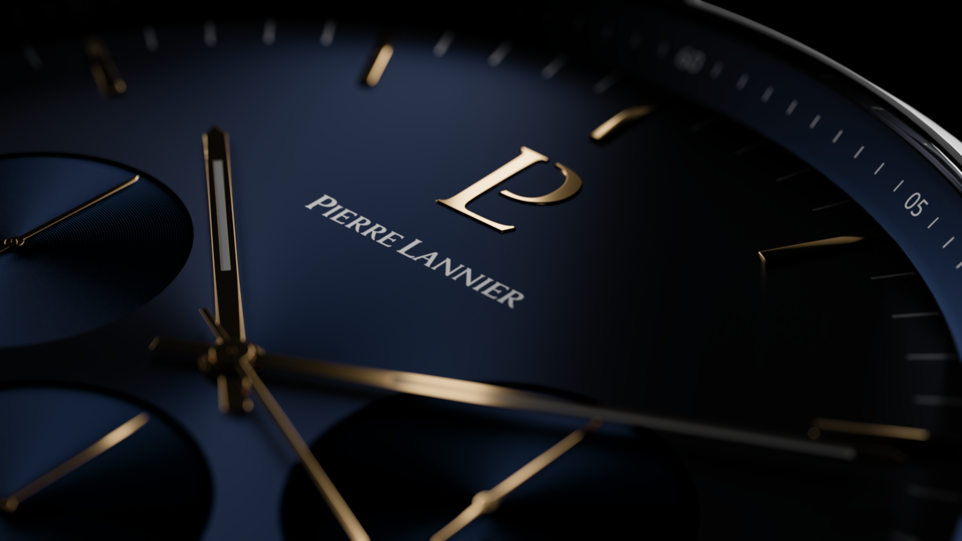
I will use this 3D render of a watch shot made in Blender, it was rendered in ACEScg with the Z. You can download it at the end of this post, alongside the node graph I use for Depth Blur.

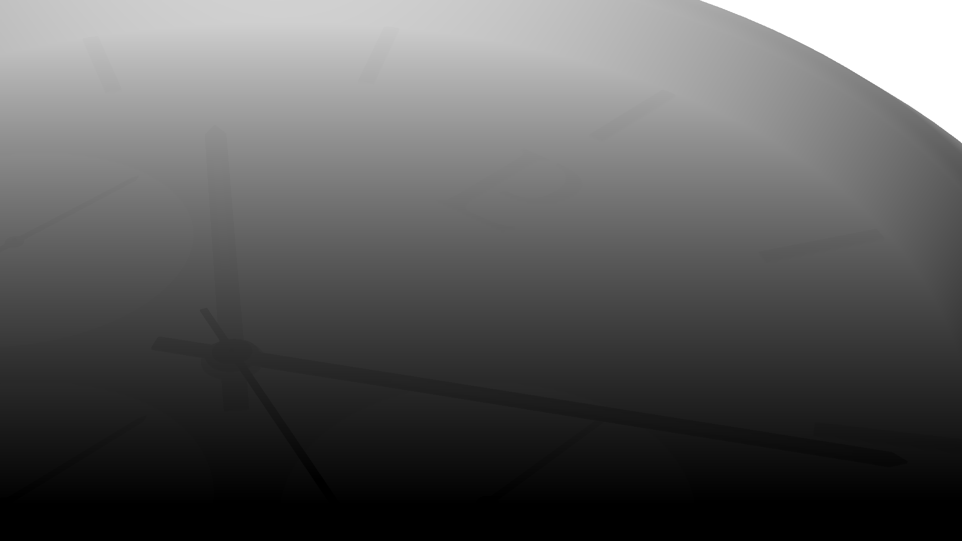
Feed in your image (make sure it has a Z channel; you can check for "z:" at the bottom of the viewer. You'll need to set it, as it's not set by default). Set the mode to "Aux to color" and the channel to Z. You should now be able to see the Z map in the viewer, even if it’s completely blown out. What we want is to map a 1D value to the RGB color channel of the viewer, so ensure you're viewing the RGB channels, not the Z channel (which you can select at the top of the viewer).

Z Map before remapping, all values are clipped out.
Z Map after remapping to 0-1. Note that the backdound is at infinite. We’ll fix that in the Vari Blur node.
Enable remapping, and use the sample min and sample max controls in the viewer to define the minimum and maximum values. If you have an infinite background, do not select it; instead, select the furthest point of the objects you want to blur. Once you’ve done that, adjust the two values slightly to avoid pure white or pure black, as we want to ensure the entire range is covered without losing data.
Now, if you connect the Copy Aux output to the VariBlur blur image input, you should get a blur falloff from top to bottom, or vice versa, depending on how you see it:
As expected, we don’t yet have control over where the image should be sharp. We just need to add one more thing.
The zone of sharpness can be viewed as a zero value in the blur image. To achieve this, we need a curve to define where its value will be set to 0. So, grab a Color Curve node and draw a "V" shape (or an "A" shape, depending on whether your Z map is flipped). Don’t forget to uncheck the Alpha channel checkbox:
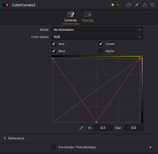
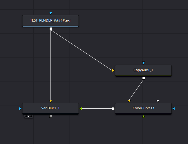
The node graph I use to blur CG images.
With such a curve, the focal point is set midway through the image depth. To adjust the DoF, simply smooth the curve. Now, to rack focus, you just have to slide the whole curve left or right, and of course, you can keyframe it to follow the element you want in your scene. (Enable the Animated Color Correct instead of No Animation).
You can also note that:
You can now play with the settings of the VariBlur to create the look you like the most for your image.
If you have a depth map that extends to infinity, you can use the blur limit slider to avoid weird artifacts between near and far elements in your image.
What’s next ?
I hope Black Magic will start to fix such a problematic node as the Depth Blur; it's just a pain to work with it.
Even though this method covers many of the problems I had with the Depth Blur node, I still find that we're missing an efficient way to control depth blur in Fusion. Even if it were usable, functionality would still be missing. I would love to have a way to use a kernel image with a node like the Depth Blur or VariBlur; it would be such a game-changer. Black Magic wouldn’t look like clowns compared to The Foundry, which has been supporting proper Depth Blur and Bokeh for 20 years. Who knows, maybe they’ll do that in the future, I hope…
The Files Used in this article:
If you want to try it out for yourself, you can download the files used in this article: node graph and input image. You’ll be redirected to Infomaniak KDrive to download the two files.
Thanks for reading this article !